Saturday 26 March 2022

Setup OpenHasp on lanbon L8 with HomeAssistant


 So my Lanbon L8 light switches were seriously buggy. Problems included;

  1. Mesh WiFi network was flawed and consistently losing connectivity
  2. Artifacts on the screen and buttons in a stuck mode
  3. Random rebooting of the switches
  4. Sluggish response from the touch screens
  5. Firmware doesn't automatically update, requires contact with supplier to do anything.
  6. Doesn't easily working with Home assistant

So, I had a look at what custom firmwares were available and found this;

Custom Firmware on Lanbon L8 LCD Touch Switch | Blakadder's Smarthome Shenanigans

Which was pretty good, but still lacked the detail of how this things works, just sort of showed how to get started. Thought it would be a good idea to go into some detail for new comers.

This article will walk through the firmware to configuration on home assistant including a few extra learnings...

Prerequisites;

  1. USB to serial (ardiuno writer) (like this CP2102 module USB to TTL serial UART STC download cable PL2303 Super Brush line upgrade for arduino|Integrated Circuits| - AliExpress)
  2. A LanBon L8 light switch
  3. Recommended - Ethernet cable, dupont connectors and dupont crimper
  4. Home Assistant (Supervised) 
  5. Home Assistant Add-on  "Mosquitto Broker" (MQTT broker addon)
  6. Home Assistant Add-on "Terminal & SSH"
  7. Home Assistant Add-on "HACS repository" (GitHub - hacs/integration: HACS gives you a powerful UI to handle downloads of all your custom needs.)
  8. From the HACS repository install the "openHASP integration"
  9. On your PC you will need;
    1. Install Arduino IDE
    2. Install ESP driver support (Installing — Arduino-ESP32 2.0.2 documentation (espressif.com))
    3. Install pyserial
    • Command is "pip install pyserial"
      • I don't remember if python came with the IDE, but you may need python for this as well if it didn't

Do a search after this, you should find the file "esptool.py" in one of you directories under "arduinodata"

I am going to assume you have installed all the above and you have some experience with the above...

Connecting the Lanbon L8

Not going to reinvent the wheel... BlakAdder explains it well see pictures, i used the same method, old ethernet cable with dupont attachments + I also used a small crocodile clamp to short IO1 and GND

Connection\Mapping between the USB to serial converter and the L8 is;

USB   | L8
RX     | TX
TX     | RX
IO1    | GND  (this is what tells the device you are writing the ESP chip inside it)
GND | GND
+5v    | +5v

Any work you do with the ESP memory IO0 must be in GND
If you hooked in correctly (with IO0) you should get a white screen (NOT the lanbon OS booting up)


Backup;

You can skip this step, but i like to have a backup of the working image in case this doesn't work and need to flash it back.

*****IMPORTANT ***** Everytime you do an action with the L8 and ESP memory you will need to reboot it.

* Run in administrative command prompt from the esptool.py directory

Please note my COM port was COM3, you will need to find yours (best is to load the Arduino IDE and take a look at "Tools->Port")

esptool.py --port COM3 --baud 921600 flash_id

Read the memory size (mine was 8MB)


Reset the device (this means disconnect +5V and reconnecting it), then;

esptool.py --port COM3 --baud 921600 read_flash 0 0x800000 c:\temp\lanbonL8OriginalFlash.bin

--The 0x800000 will equate to 8MB of memory

Writing OpenHASP to the device

Download openHASP image from here; Releases · HASwitchPlate/openHASP · GitHub

I did this with version 0.6.2 -https://github.com/HASwitchPlate/openHASP/releases/download/v0.6.2/lanbon_l8_full_8MB_v0.6.2.bin

  1. Reset the device (this means disconnect +5V and reconnecting it)
  2. Erase the current OS
    • esptool.py --port COM3 erase_flash
  3. Reset the device
  4. Write the openHASP image to the device
    • esptool.py --port COM3 --baud 921600 write_flash 0x0 lanbon_l8_full_8MB_v0.6.2.bin


Configure the "Plate"

Thats it, you have now installed openHASP on the Plate, next step configuring it;

For reference here is how it fits together;


Once write confirmed remove IO0 from Ground and reboot.Should show this 


Add to wifi manually (should get an IP pop up)

Then you should see this;


In a web browser put the IP that it got from DHCP.

Now I had an issue that after a few minutes the web console stopped responding, this is a known issue with the serial console. Too stop this happening we have to shutdown the console once the Network switches on.


In the "file editor" on the web page, add this line;
service stop console

Should look like this;


I uploaded mine (couldn't figure out how to edit files in the editor)

Next enter the MQTT broker details;


Note the HASP node name is the device name going forward

Save settings then reboot the device (can do from the web interface now)


If you have done everything as expected you should be able to see it on the MQTT broker using MQTT explorer.

Next is configuring the GPIOs for the relays and mood lights. You can do this manually but its far easier using MQTT explorer;

Send the following json to hasp/[mqttnodename]/config/gpio

{"config":[197658,263456,329249,655628,655886,656155,0,0]}


See example:


At this point I highly recommend you check the web page of the Plate to make sure the PINs are now configured.


Setting the display up

So all the base setting up is done, now we need to draw up the GUI. I am not going to go into something complex, rather I will give you my first "pages.jsonl" to work with;

{

"page": 0, 

"id": 1, 

"x":0, "y":0, "w":80, "h":20, 

"comment": "Time in the top left", 

"obj": "label", 

"text_color": "#FFFFFF", 

"text": "00:00", 

"align": "left", 

"bg_color": "#2C3E50"

}

{

"page": 0, 

"id": 2, 

"x":160, "y":0, "w":60, "h":20, 

"comment": "Temp", 

"obj": "label", 

"text_color": "#FFFFFF", 

"text": "00.0", 

"align": "right", 

"bg_color": "#2C3E50"

}

{

"page": 0, 

"id": 3, 

"x":220, "y":0, "w":20, "h":20, 

"comment": "Temp sign", 

"obj": "label", 

"text_color": "#FFFFFF", 

"text": "°C", 

"align": "right", 

"bg_color": "#2C3E50"

}

{

"page": 0, 

"id": 6, 

"x":0, "y":300, "w":80, "h":20, 

"comment": "tab nav on the bottom, prev", 

"obj": "btn", 

"action": "prev", 

"bg_color": "#2C3E50", 

"text": "\uE141", 

"text_color": "#FFFFFF", 

"radius": 0, 

"border_side": 0, 

"text_font": 28

}

{

"page": 0, 

"id": 7, 

"x":80, "y":300, "w":80, "h":20, 

"obj": "btn", 

"action": "back", 

"bg_color": "#2C3E50", 

"text": "\uE2DC", 

"text_color": "#FFFFFF", 

"radius": 0, 

"border_side": 0, 

"text_font": 22

}

{

"page": 0, 

"id": 8, 

"x":160, "y":300, "w":80, "h":20, 

"obj": "btn", 

"action": "next", 

"bg_color": "#2C3E50", 

"text": "\uE142", 

"text_color": "#FFFFFF", 

"radius": 0, 

"border_side": 0, 

"text_font": 28

}

{

"page": 1,

"id": 101, 

"x":0, "y":30, "w":240, "h":80, 

"comment": "relay1", 

"obj": "btn", 

"toggle": true, 

"text": "\uEA70 Dining Room", 

"mode": "break", 

"align": "center", 

"groupid": 1

}

{

"page": 1, 

"id": 102, 

"x":0, "y":120, "w":240, "h":80, 

"comment": "relay2", 

"obj": "btn", 

"toggle": true, 

"text": "\uF1E1 Kitchen Bench", 

"mode": "break", 

"align": "center", 

"groupid": 2

}

{

"page": 1, 

"id": 103, 

"x":0, "y":210, "w":240, "h":80, 

"comment": "relay3", 

"obj": "btn", 

"toggle": true, 

"text": "\uF054 Outdoor Trampoline Area", 

"mode": "break", 

"align": "center", 

"groupid": 3

}


Here are a couple of key details;

  • Page 0 is common for all pages (header and footer page) 
    • The time and temperature will be fed back (to the placeholder) from the HA server they do not live on the plate at all.
  • The id will be referenced later in Home Assistant
  • Special images are in the font and can be used using \uABCD
  • Groupid relates to the GPIO port it will use

Okay, now upload it via the web page via the HASP Designer, save and REBOOT.

Should look something like this... But without the time and temperature (as HA isn't configured)


The switch should now work with the relays even with out home assistant, so you can detach the cables and stick it back on the wall...

Configuring Home Assistant

Open up the terminal on the home assistant web page.

Goto the config directory

cd config

I am going to assume you know how to use the vi editor or something similar, not going to go into it here, google vi editor if you dont know how to use it...

vi configuration.yaml


Insert the line "openhasp: !include openhasp.yaml"

Write and quit the file.

You could insert the code into this file but it would be long and painful, not recommended

vi openhasp.yaml


DO NOT USE TABS in the file, it will not parse correctly if you do.

  • Sensor.time I added and entity to Home assistant to show time on unit
  • Sensor.hue is a philips motion sensor that I am pulling the temperature from.
Check the configuration on Home assistant (Under Configuration->Settings)
Hit "check configuration"

So long as it parses hit the "RESTART" under Home Assistant


Summary


Hope you enjoyed this tutorial, i put it together so i remember what i did next time i have to change something.
All the issues I raised at the start are resolved with this firmware, so highly recommended, but not for those with no will to tinker....

  1. Mesh WiFi network was flawed and consistently losing connectivity - Resolved
  2. Artifacts on the screen and buttons in a stuck mode - Resolved
  3. Random rebooting of the switches - Resolved
  4. Sluggish response from the touch screens - Resolved
  5. Firmware doesn't automatically update, requires contact with supplier to do anything. - Resolved
  6. Doesn't easily working with Home assistant - Resolved

Saturday 29 July 2017

Setting Up BLTouch on infitary M508

Setting Up BLTouch on infitary M508

**General note I take no responsibility for any damage that may occur to you in this implementation. This is how I configured it but no guarantees.

So levelling is a pain, so I thought this is one problem that needs to be fixed.
Bought the Clone BLtouch from aliexpress... seemed fine but comes with lots of parts like dupon connectors. Which means you will need a crimping tool to put it together.
The other part you need is an extension for the 5 cables coming out of the BLTouch, the ones that come with the BLtouch are incredibly short.


Additional stuff you need to product;
* Crimping tool
* Additional wires
And depending on how good your crimping skills are you might need additional dupon connectors.

Alternatively you could just by a 2pin to 2pin (Black and White) cable with the 2piece dupon connectors attached and another 3pin to 3pin (Orange, Red & Brown) cable with the 3 piece dupon connectors.

Mount for the BLtouch

I took an existing mount from thingiverse, but that didn't really work well as it was too high according to the spec.

 Was about 15mm high when it needed to be about 8mm.

So I modified the shape on blender. You can find it here. (Thingy item 2459032)


Wiring diagram

First things first. I spent hours trying to figure out how to connect this to the M508. The board looks like this; (BTW this seems to be the same board as the Alunar)

You don't really need the brown GND, but I added it for good measure.
For this you need to disconnect the Z-Min sensor. You are replacing it with the bltouch.
DONT AUTO HOME until you upload firmware.

So where you should be up to now is that the red light on the bltouch comes on and does 2-3 ins and outs, but will really not be able to do anything.

Changes to Marlin Firmware

You will need Arduino IDE for this next bit.

The version of marlin I ran this on was 1.1.4. The versions seem to be very different so can't guarantee this will work on a newer version.

Overall, download the latest release (or if you can find it 1.1.4)

The following is what I changed. Will also put my firmware here but I use PETG filament so the ABS Settings are off.


Once you downloaded the firmware, open up the zip file somewhere.
Replace the configuration.h and configuration_adv.h in the marlin directory with the files from the example_configurations for the Infitary-i3-M508.

Now open the marlin.ino file and it should load up the arduino IDE.

***First off the default this board is defined as a RAMPS 1.3 board (whatever that means)
#define MOTHERBOARD BOARD_RAMPS_13_EFB
This is on its own right is not a problem. If you follow the chain of files to the pins_RAMPS.h you will find this;
#ifdef IS_RAMPS_13 //This was defined in a different file...
  #define SERVO0_PIN       7 // RAMPS_13 // Will conflict with BTN_EN2 on LCD_I2C_VIKI
#else
  #define SERVO0_PIN       11
#endif
The problem here is that any default configuration you enable for the BLTouch will expect you to use pin 11 (SERVO0). The BTN_EN2 is not shared with this pin on the M508 so I changed it to PIN 11

#ifdef IS_RAMPS_13
  #define SERVO0_PIN       11 // RAMPS_13 // Will conflict with BTN_EN2 on LCD_I2C_VIKI
#else
  #define SERVO0_PIN       11
#endif

Now go and edit the configuration.h file with the BILINEAR leveling;
All the settings below are settings that were changed from the Marlin 1.1.4 configuration.h file. The rest I just omitted to avoid complexity.
//===========================================================================
//============================== Endstop Settings ===========================
//===========================================================================

#define Z_MIN_ENDSTOP_INVERTING false
#define Z_MIN_PROBE_ENDSTOP_INVERTING false
//===========================================================================
//============================= Z Probe Options =============================
//===========================================================================
#define Z_MIN_PROBE_USES_Z_MIN_ENDSTOP_PIN
#define Z_ENDSTOP_SERVO_NR 0   // Defaults to SERVO 0 connector.
#define Z_SERVO_ANGLES {10,90}  // Z Servo Deploy and Stow angles (10,90) is for BLTOUCH.
#define BLTOUCH
#if ENABLED(BLTOUCH)
  #define BLTOUCH_DELAY 1000   // (ms) Enable and increase if needed
#endif

 //SET FOR BLTOUCH - WHERE IS THE PROBE COMPARED TO THE NOZZLE
#define X_PROBE_OFFSET_FROM_EXTRUDER -25  // X offset: -left  +right  [of the nozzle]
#define Y_PROBE_OFFSET_FROM_EXTRUDER -45 // Y offset: -front +behind [the nozzle]
#define Z_PROBE_OFFSET_FROM_EXTRUDER -2   // Z offset: -below +above  [the nozzle]
//originally 205 but m508 can go to 215 (Not related to bltouch)
#define X_MAX_POS 214
#define Y_MAX_POS 214

//===========================================================================
//=============================== Bed Leveling ==============================
//===========================================================================
#define AUTO_BED_LEVELING_BILINEAR
  //SET FOR BLTOUCH - CHECK ON PRINTER FIRST TO BE SURE
  #define LEFT_PROBE_BED_POSITION 34
  #define RIGHT_PROBE_BED_POSITION 180 //Bed Max X - Left probe
  #define FRONT_PROBE_BED_POSITION 55
  #define BACK_PROBE_BED_POSITION 159 //Bed Max Y - Front probe
//SET FOR BLTOUCH TO AVOID DAMAGE TO PRINTER! Sensor will be above bed.
#define Z_SAFE_HOMING
#if ENABLED(Z_SAFE_HOMING)
  #define Z_SAFE_HOMING_X_POINT ((X_MIN_POS + X_MAX_POS) / 2)    // X point for Z homing when homing all axis (G28).
  #define Z_SAFE_HOMING_Y_POINT ((Y_MIN_POS + Y_MAX_POS) / 2)    // Y point for Z homing when homing all axis (G28).
#endif
//=============================================================================
//============================= Additional Features ===========================
//=============================================================================
#define EEPROM_SETTINGS // Enable for M500 and M501 commands - Allows you to save BLTouch Z offset
#if ENABLED(EEPROM_SETTINGS)
  // To disable EEPROM Serial responses and decrease program space by ~1700 byte: comment this out:
  #define EEPROM_CHITCHAT // Please keep turned on if you can.
#endif
//SET FOR BLTOUCH - still not sure why 3?
#define NUM_SERVOS 3 // Servo index starts with 0 for M280 command


#define DEFAULT_NOMINAL_FILAMENT_DIA 1.75   // (mm) Diameter of the filament generally used (3.0 or 1.75mm), also used in the slicer. Used to validate sensor reading. - I fixed this while I was at it. It was set to 3.0mm when I use 1.75mm

All items in green are items that require you to check on the printer and fill in those spots.
The Z_PROBE_OFFSET_FROM_EXTRUDER settings will most likely need to be adjusted as part of levelling calibration process.

Hopefully, if everything went well you can compile. If successful you can now upload the file.
Connect your device via USB it should come up as a new com port.
Change the board and processor under "tools" menu;
Board should be "Arduino\Gemuino Mega or Mega 2560"
Processor should be "ATmega2560 (Mega 2560)"

Now upload (CTRL+U). It will compile then upload. Don't disturb it. If it fails to upload, try again.

Testing

On whatever tool you have that can run serial commands to the printer run these. (I use octoprint)

Under the Terminal type; (Don't type the ; and comments after it:))
M280 P0 S10 ; pushes the pin down M280 P0 S90 ; pulls the pin up M280 P0 S120 ; Self test – keeps going until you do pin up/down or release alarm M280 P0 S160 ; Release alarm 
M119 ;shows status of x,y,z min they should all be open.
M280 P0 S60 ;Puts the the BLTouch in test mode dont skip this test.
M119 ;Take note that everything is "open"
Now push the pin upwards, should be a very light touch and not hard. The light should come on.
If your BLtouch is like mine, it will push the pin down again in a few seconds.
Before it pushes the pin down, put in the M119 again.

You should see Z_Min triggered. If it isn't something has gone wrong, and it is way to hard to tell you where. Could be wiring, could be firmware... try narrowing it down. You shouldn't need the resistors or anything else.

First calibration

So we are nearly there. Need now to make sure that the nozzle is nearly touching the heat bed when the Z is zeroed.

For this next step have you finger over the power button to shut it off if it doesn't go as expected. What I mean is that if the BLTouch isn't working as expected the auto-homing will push the nozzle into the bed and potentially damage something!

Go back to the terminal and type;
M851 ; this should give you the item I highlighted in orange a while back
G28 ; home - FINGER OVER POWER BUTTON!
G1 Z0 ; this will set the nozzle at Z0 at least what it thinks is 0.

If the nozzle is too high above the bed then the Z_PROBE_OFFSET_FROM_EXTRUDER  needs to be a lower number (e.g. -2.5 instead of -2). If it's pushing into the bed, then it needs to be larger (-1.5 instead of -2). 

To figure out how much to put in, you will need a number that slightly digs in the bed (should push the springs) and play with the Z on the actual m508 (under prepare), move it up till you have a figure (e.g +0.2mm)

Let's say the figure I had was -2 from M851. Now I need to add the 0.2mm, this should give me a figure to put in = -1.8

To change the z offset programmatically you can type in; Have a piece of thin a4 paper under the nozzle.


M851 Z-1.8G28 ; homeG1 Z0 ; this will set the nozzle at Z0 at least what it thinks is 0.
If the paper is slightly hard to move but still moves under friction of the nozzle, you are good to go. If not, keep adjusting the M851 Z value till it does.

Once you are done commit to memory (EEPROM). Type in the terminal

M500 ; commit to memory

Autoleveling the bed

Now in the menu do prepare->bed levelling
or type G29 from the terminal. It should measure 9 points across the bed. (these points probably need tweaking but for now that should be fine)

G29 in startcode

Make sure to do a leveling command at the beginning of each print (this is not a must, but good measure)

I use Slic3r and I put it in the "Printer Settings->Custom G-code"
After G28 on the next line put in G29


Printing a test print

Use this to test the calibration and auto bed levelling is working
https://www.thingiverse.com/thing:29028/#files


Issues encountered

This thing burned up a weekend nicely.
First off where to connect was painful, then the fact that it wasn't listening to commands from the firmware. This was caused by the pins_RAMPS.h file using the wrong port!!!!

After figuring that one out when I hit auto-home it would keep on pushing the heat plate and not stopping.
It ended up being a mistake I made in the firmware. I forgot to add #define Z_MIN_PROBE_ENDSTOP_INVERTING false
was set as true while I did setup Z_MIN_ENDSTOP_INVERTING  as false. This is a must.

Overall its now working. Time will tell how well it actually works. Might have to monitor start of prints for a while.

Links;

https://locxess.de/3d/BLTouch_Anleitung_englisch.pdf


Friday 28 July 2017

newbie 3D Printing

Newbie 3D Printing

So I got my first 3D printer. It is an Infitary M508 from aliexpress.
With little to no experience wasn't sure what I was looking for...

**BTW for later the filament for this unit is 1.75mm and Nozzle head is 0.3mm

It arrived relatively quickly and as a kit. When they say a kit they mean a kit:)

When you open the box you will see the 5 step motors (2 for Z-axis, 1 for Y-Axis, 1 for X-Axis and an extruder step motor), along with a circuit board (Arduino board custom made for 3d printers), power supply, LCD and SD slot and frame.

They also put all the videos and firmware for you on an SD card which is a nice touch. No manuals are printed out anywhere though.
 

Spent half the day peeling the brown tape from the frame and then followed the youtube videos to put it together. Overall there are a few complex pieces and making sure you are always on the correct side of the project is pretty important! put a few things the wrong way around, only to find later, for example, that I put the main Y axis screws in backwards *doh*.

The Y-Axis belt required a bit of time as you need small hands and a second pair of hands if available.

The X-Axis was even more painful, but I got through it.


Power was pretty straight forward, and I can't say it was to complicated. Just had to use a lot of zip ties to tidy up the cables. (you will need to buy quite a few small ones)

After putting together the cables, I highly recommend not following the video directions for the extruder cables they should go to the side not over the top, but if you aren't certain just follow the video. You will see what I mean later:)


Once it was assembled and I powered it on, it all seems to work with no smoke. That was a good sign. You can move the axis from the menu (Firmware is already installed on the Arduino - firmware is called Marlin, that's for a different day).
Could move the X axis and Y axis fine, but Z was making a grinding noise and getting stuck more often then not.
After loosening one side of the Z-Axis long screw shaft from the motor the Z axis moved freely on only one step motor. It would appear that the Z-axis screw wasn't fully aligned with the motor and with the X-Axis mount, there is no way to make it align better (as far as I can see), so I released a few screws (specifically the ones on the brass Z-axis to X-axis carriage which have the Z-axis shaft run through it) to give it the space it needs to move freely.

Alignment of the nozzle and the heating bed seemed rather simple just moved the Z axis limiter switch and twist the Z-axis to get the right height till they seemed to touch.
(limiter switch is the little switch which tells the arduino when you get to the minimum point, so it doesn't grind the motors)

After fixing that problem I tried loading filament. There is an easy way to do this.
1. Cut the filament with the cutter so that it is sharp on one end.
2. Providing you are using PLA, under the prepare menu goto preheat PLA, this will warm up the Nozzle to 190degrees.
3. Once it reaches 190, go back to the prepare menu and press change filament.
4. It will then try to retract the previous filament (which doesnt exist), wait a couple of seconds to let it go through its unloading cycle.
5. The put the filament in the small hole on the extruder stepper and press the round button. It should start loading the filament:)
Took me a while to figure out how to load it...


Okay so first a couple of pointers for newbies;
1. 3D printers print gcode files which are just machine instruction sets for vectors and movements (including commands for heating elements etc....)
2. You will need to install something like cuda on you PC to convert STL files which are exports from CAD type software to something your printer can understand. This is provided on the SD card with this unit (It can also be downloaded from the web)
3. The SD card has some gcode files on it already ready to test, so just insert that to test it.


So attempt 1 to print... First of DON'T DO THIS!
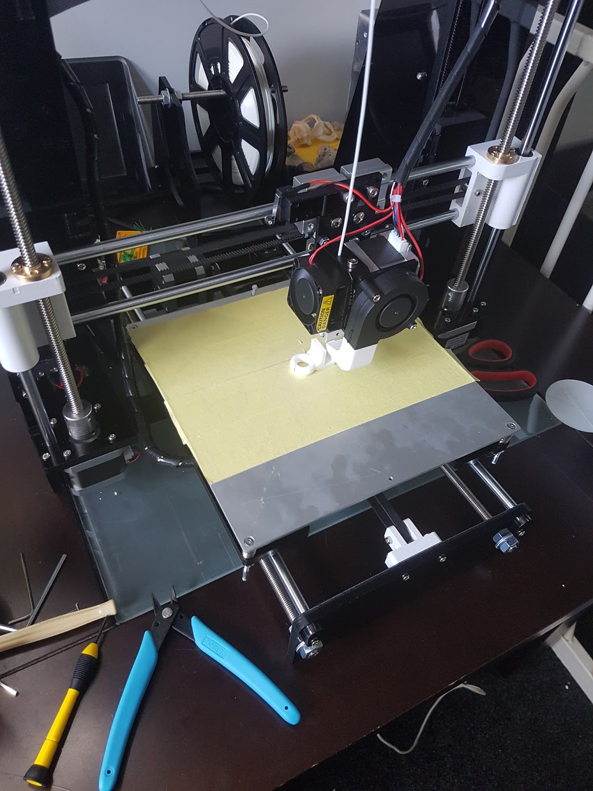
I didn't put down any tape (the yellow stuff in the picture above) because i didn't understand why I needed it (will explain later). I then proceeded to print the first file by selecting it from the menu on the SD card.
The bed warmed up, then the nozzle warmed up. (They do this so the nozzle doesn't start oozing while you wait for the heated bed)
The bed was not level, which means the nozzle nicely dug a long groove into my heated plate. quickly pulled the plug and read up on levelling.

So this is one thing I would probably make sure I had as a feature when I bought a 3d printer. The M508 does not come with auto levelling built in.
Levelling includes disabling you step motors (in the menu), taking a sheet of A4 paper and moving your nozzle across 4 different points of the bed to make sure it is barely touching the paper, by rotating the screws in the correct location. (there are other more scientific ways to do this, but this is simple enough for most).

Attempt 2... okay so I tried levelling... but didn't use the method with an A4, rather I tried eye balling it.
It started and didn't scrape the surface that was good, and then it started to print, but the filament just kept on being pushed around by the nozzle and detaching from the bed... stopped that and read more...

After reading more learned that a technic to make sure things stuck to the bed was to use painters tape (they yellow tape), so stuck that on and went on attempt 3.

Once again it started up but the same thing happened... the filament just detached from the bed!!!

Played with levelling for a good 2 hours, cause I didn't know what good looked like. Finally got to the point where it was slightly squishing the filament on the bed and it started to print properly. (A4 sort of worked:))

*Your gut feel will tell you that the head has got loose filament hanging from the heating process that is pushing the filament off the bed. That isn't the problem your bed is just of range. Do the levelling. It can also be a temperature issue but start with that one first.


BTW, if you haven't bought a printer, don't expect it to printing anything in a hurry. It takes hours!

After less than a couple of hours, my kids wanted me to print something for them, so I went over to thingiverse and found a Pitbull. I tried shrinking it on cuda (by changing the scale - so it wouldn't take so long). Generated the gcode and put it to print.

It started printing just fine, until the hind legs would just detach from the base mid print (even with the levelling done and the tape). I thought I was doing something wrong!! tried glue sticks, tried re-levelling, nothing worked. the legs kept coming off!!

What I quickly learned was that the surface area of the leg was just way to small for it to stick properly. I modified the STL using blender and put a bigger footing around it and it worked just fine.

So that's all from me today. If you got this far you are at the beginning of the journey:)


Saturday 5 September 2015

The Silent Era

Well this is my first ever blog, but I thought I might as well start with a subject I am enthusiastic about.

Technology has been evolving at exponential rate, but the concept hasn't changed much. We seem to want things faster and quicker to meet our immediate needs.

The real change seems to have occurred with the uptake of mobile devices and improvement of internet infrastructure. These too have allowed businesses to grow and evolve to areas they never thought to grow. It would seem that the never ending appetite for data also just keeps on going especially with the emergence of A.I\Machine learning with data analysis.

The question I keep on hearing is "What is the next big innovation?"...

So lets see where we are headed in the immediate future;
Mobile devices are overtaking every other device. Soon to be capable of replacing full blown PC's by just docking them probably over wireless.

Augmented reality, a theory that was in the good old Star trek with the "Holo deck" soon to become a reality with the Microsoft Hololens. Unlocking a whole lot of business possibilities we never contemplated - the designing world is about to get a massive revamp\disruptor; Architecture, Building, interior design, engineering, even heavy equipment operators might be able to see where underground cables are by just using this headset.


Bionics is evolving to allow us to replace body parts with metals and plastics.
A.I and robotics is around the corner leading to an array of capitalistic questions as long as my arm, but lets talk about that later.

In my opinion there is one big next step for us, and that is what I call the "silent era".
The silent era is when humans control electronics by pure thought. When the phone becomes the medium for cognitive actions. Things like sending a text by thinking about someone and something to say, or getting the air conditioner to switch on without even looking at it. How much simpler can life get then that?
So why the "silent era"?
Well when we start using our mobile to text our thoughts I wonder how much talking we would actually do?

This might not happen for the next 10-50 years, but I think it is just the natural evolution of technology. I wonder how far off I will actually be...